Tutorial: build and set up the rig
How to go from parts to a working maze. The design is deliberately reconfigurable: the floor is a grid of threaded holes and the walls slot into aluminium posts, so the same rig becomes a four-arm radial maze, an eight-arm one, or a binary decision tree by moving walls rather than building something new.
What you are building
flowchart TB
    subgraph rig["The rig"]
        top[White maze top<br/>reflects the infrared back]
        maze[Maze floor plate<br/>infrared transmitting<br/>with movable walls]
        cam[Infrared camera<br/>below the plate, looking up]
        ill[Infrared illuminator<br/>below the plate]
        spk[Ultrasonic speaker]
        frame[Frame and legs]
    end
    pc[Computer]
    ard[Arduino<br/>optional]
    rec[Recording system<br/>optional]

    cam -->|USB| pc
    pc -->|audio interface| spk
    pc -->|serial| ard
    ard -->|TTL| rec
    maze --- frame
    ill -->|up through the floor| top
    top -->|reflected back down| cam
The room is dark and everything optical happens underneath. The camera and the infrared illuminator both sit below the floor plate, looking up. The plate transmits infrared, so light from the illuminator passes up through it, reflects off the white top of the maze, and returns down to the camera.
The camera therefore sees a bright field: the lit white top, seen through the floor. An animal in the maze sits between the two and blocks that returning light, so it appears black. That dark silhouette against the bright top is the whole of the detection. It is the same in both configurations.
This is why the binary threshold and the detection sensitivity work the way they do: an empty arm is bright, and an occupied one drops.
Parts
Structure
| Part | Specification | Notes |
|---|---|---|
| Floor plate | 700 x 700 x 10 mm, black, infrared transmitting | Drilled with a regular grid of M3 holes so wall posts can go anywhere |
| Maze top | 3D printed in white, one per configuration | Reflects the infrared back down to the camera. This is the bright field the animal is seen against, so it is not optional. Print in white filament: the brightness of the picture depends on it |
| Wall panels | 50 x 50 x 3 mm or 100 x 50 x 3 mm acrylic, black | About 50 with spares. The taller ones stop mice jumping out when the maze is uncovered: the eight-arm auditory maze uses those, the four-arm tactile maze the shorter ones |
| Posts | MakerBeam XL, 15 x 15 mm, 50 or 100 mm long, black anodised | Panels slide into the T-slots. Match the post length to the panel height |
| Bolts | M3 x 16 mm with nuts, one per post | Nuts go under the floor plate |
| Legs | 50.8 x 50.8 x 1.6 mm box section, 880 mm | Four, with plastic joints and feet |
| Horizontal bars | 660 mm | Four, around the outside |
| Feet | M6 bolts and nuts | One per corner, for levelling |
Full measurements, including the dimensions taken from the Rosenberg maze this design started from, are on the dimensions page. Suppliers the lab used are on the materials page.
Electronics
| Part | Notes |
|---|---|
| Infrared camera | Must have the infrared filter removed. The lab used an ELP USB camera |
| Infrared illuminator | Even coverage matters more than brightness |
| Ultrasonic speaker | With a published frequency response, or the means to measure one |
| Audio interface | 192 kHz capable |
| Arduino Uno or Nano | Only for TTL synchronisation |
| Adafruit PCA9685 | Only for the tactile paradigm's servos |
Printed parts
All in hardware/3dmodels/ as FreeCAD sources and STLs: the camera housing, the electronics enclosure, the movable wall mechanism, the transfer tunnel and the reward chute.
The maze tops are printed too, and there is one per maze configuration: a four-arm top for the tactile decision tree and an eight-arm top for the auditory maze. They go in hardware/3dmodels/maze_parts/maze_cover.
Assembly
1. Floor and frame
Bolt the legs to the floor plate with the M6 bolts and fit the feet. Assemble the box-section frame around the outside with its plastic joints. The lab attached the frame with velcro so it can be lifted off.
Level the plate before going further. An animal on a sloping floor has a side bias, and you will spend a long time looking for that in the data.
2. Walls
Bolt posts into the grid at the positions your configuration needs, then slide the acrylic panels into the T-slots between them. A four-arm maze needs roughly 50 panels and 50 posts.
Configure a simple layout first and run an animal before building something elaborate.
3. Camera
Mount the camera centrally below the floor plate, looking up through it, far enough back to see the whole floor plus both entrance zones. The camera housing in hardware/3dmodels/camera_holder/ is designed for this.
Everything the camera sees arrives through the plate, so keep its underside clean. A smear or a scuff is a permanent dark patch in the picture, and if it falls inside an arm box it shifts that arm's baseline.
Two things to get right:
- The whole maze in frame, with margin. You will draw arm boxes on this picture, and an arm cut off at the edge cannot be monitored.
- Nothing moves afterwards. The arm boxes are saved in pixel coordinates. Bumping the camera means redrawing them, and a session recorded with stale boxes is lost.
4. Lighting
Place the illuminator below the plate, beside the camera, and fit the white top. Then turn the room lights off: sessions run in darkness, with the infrared the only illumination.
Look at the picture and check the white top reads evenly bright across every arm. Detection compares each arm against its own empty brightness, so uneven lighting is tolerable but drifting lighting is not. Stray visible light reaching the camera is what causes drift, which is why the room is dark rather than merely dim.
5. Speaker
Position it so every arm receives a comparable level. A speaker at one end makes near arms louder, which the calibration curve cannot fix because it corrects frequency, not position.
Measure the level at several arm positions with a sound level meter and adjust placement until they agree.
6. Arduino, if using TTL
Upload firmware/ttl_bnc/TTL_bnc.ino, connect pin 8 to the digital input of your recording system, and note the COM port. See firmware.
Configuring the tactile maze
The auditory configuration above is the simpler one. The tactile maze adds gratings, reward ports and their electronics.
Walls and gratings
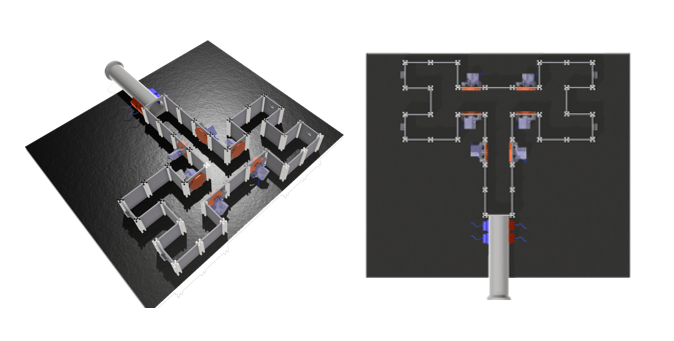
Build the two-level binary decision tree: an entrance corridor, a first junction, then two second junctions, each leading to a pair of reward arms.
Fit three pairs of gratings, one pair before each junction, mounted facing
each other across the corridor so the animal whisks against one on each side as
it approaches the choice. The printed parts are in
hardware/3dmodels/archive/gratings/, and the movable wall mechanism that
carries them is in hardware/3dmodels/moveable_wall/.
Each grating has its own servo. Wire them to the PCA9685 on the channels the
firmware expects, listed on the firmware page, or change the
#define lines to match your wiring.
Check the angles before anything else. Send a command by hand and watch:
Note which angle gives vertical and which gives horizontal, then put those
numbers in grating_maps.csv. The values shipped in the repository are a
template, not a measurement of your rig.
Reward ports
One per reward arm, each combining the servo-driven dispenser from
hardware/3dmodels/reward delivery/ with an infrared emitter and detector
placed across the chute so a falling pellet breaks the beam.
Alignment matters more than anything else here. If the beam never breaks, the
servo rocks forever; if it reads broken with nothing there, every trial reports
a reward that was not given. Run firmware/arduino/testIR/testIR.ino, watch the
four readings, and drop pellets through by hand until each one registers
reliably.
Electronics
Arduino, connected by serial to the computer, driving the PCA9685 over I2C, which drives the ten servos. The four infrared detectors go to the Arduino's digital pins. A BeeHive board developed at the University of Sussex is used alongside these.
Upload firmware/arduino/servo_control/servo_control.ino, and use
firmware/arduino/i2c_scanner/ first if the PCA9685 does not respond.
First run
Check the picture
Start the application, set the camera index in Devices, and press Check camera. You should see the maze. Wrong room means wrong index.
Draw the arms
Draw entrance1 and entrance2 across the connecting corridor in that order, since entrance1 then entrance2 means entering and the reverse means leaving. Then one box per arm, over the region the animal's body occupies rather than the whole arm.
Tune the detection
Stay in the same live view. The floor should be white and anything on it black in the binary window; if the floor is grey and patchy, adjust the illumination or the binary threshold until it is not.
Move a dark object into an arm. Its box should turn red promptly and turn blue again when you remove it. With the maze empty, every bar in the readout should be green: an amber one is an arm that will trip on a shadow, so lower the sensitivity or fix the lighting over that arm.
This is worth doing before an animal is involved, because the alternative is finding out from the data afterwards. Press S to save the settled values back to the config.
Calibrate the speaker
Before any real data. See speaker calibration. Without it, louder frequencies masquerade as preferred ones.
A checklist before the first animal
- [ ] Floor level
- [ ] Camera and illuminator below the plate, white top fitted, room dark
- [ ] Camera sees the whole maze and both entrance zones, and is fixed
- [ ] Binary view shows a clean silhouette
- [ ] Arm boxes drawn and saved
- [ ] Entries and exits logged correctly for a hand-moved object
- [ ] Sound level comparable at every arm
- [ ] Speaker calibration curve loaded
- [ ] A test session runs end to end and writes figures
Additionally, for the tactile maze
- [ ] Every grating reaches both positions, and you know which angle is vertical
- [ ]
grating_maps.csvholds your measured angles, not the template values - [ ] All four infrared beams register a hand-dropped pellet reliably
- [ ] Each reward port delivers exactly one pellet and then stops
- [ ]
reward_sequences.csvdescribes the training stages you intend