The eight-arm maze
The configuration used for the auditory preference experiments: a corridor running the width of the maze with four arms opening off each side, and an entrance tunnel at the midpoint of one long side. The animal enters through the tunnel from its transport cage, which docks at the open end.
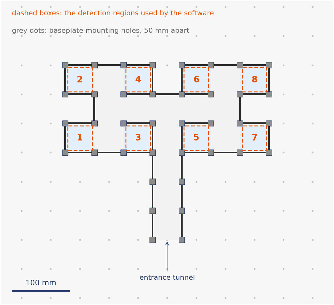
Walls are acrylic panels held between MakerBeam posts on the drilled floor plate, so the geometry is a grid: posts sit at 50 mm spacing and every panel runs from one post to the next. The dashed boxes are the detection regions the software uses, numbered as it numbers the arms.
The layout is a file, not a drawing
The plan above and the walls of the solid model both come from one file,
hardware/3dmodels/eight_arm_maze/maze_layout.json, which records which squares
of the post grid are floor, which edges carry a panel and where the boundary is
open. Nothing is traced, so nothing is distorted, and the drawing and the model
cannot drift apart about the maze.
To change the maze, redraw the layout rather than editing either output. The editor shows the post grid and lets you click the squares the animal can walk on and the edges that carry a panel.
The solid model
hardware/3dmodels/eight_arm_maze/eight_arm_maze_modified.FCStd is the model of
the rig. Alongside the maze it holds the table frame, the printed covers, the
transfer tunnel, the speaker with its grille, end caps and SpeakON connector,
the foam structure and board that carry it, the home cage with its wire lid and
water bottle, and the camera and infrared illuminator under the plate. The whole
assembly measures 700 x 960 x 1151 mm, from the feet of the legs to the top of
the speaker. Everything except the walls and posts was added by hand, because a
grid of squares cannot describe it.
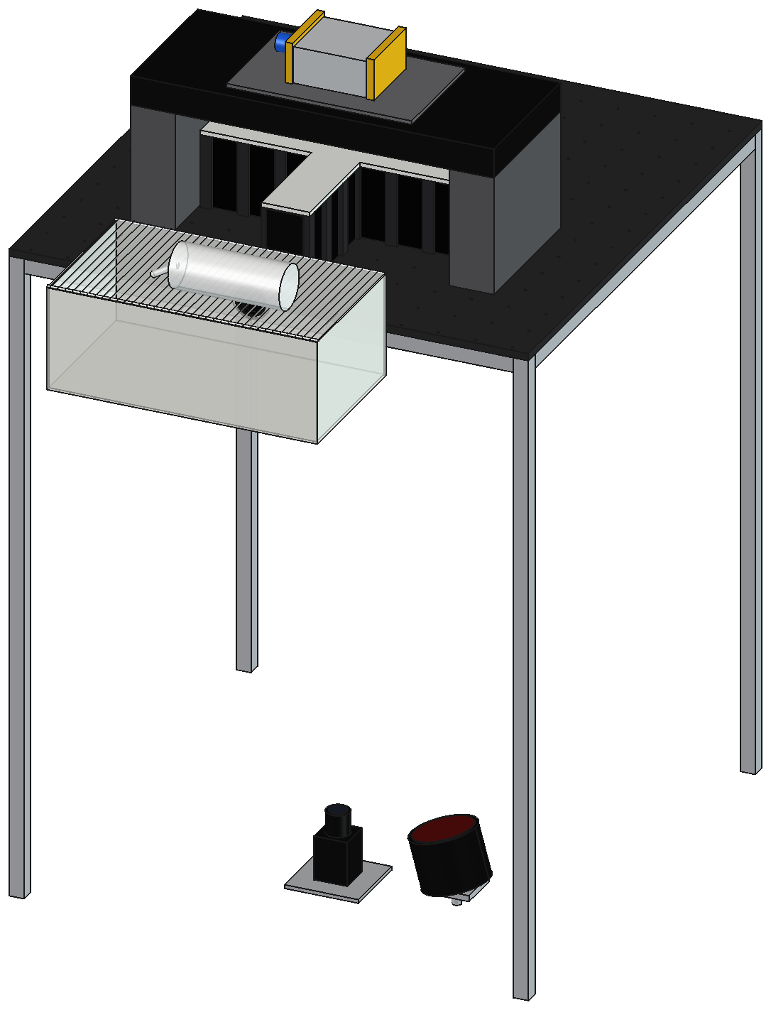
The baseplate is raised on its frame so the camera and the infrared illuminator, under the plate, can see the maze from below. The transport cage hangs off the edge of the plate at the mouth of the tunnel, so it can be docked and taken away without disturbing the maze. Sessions run with all of this in darkness.
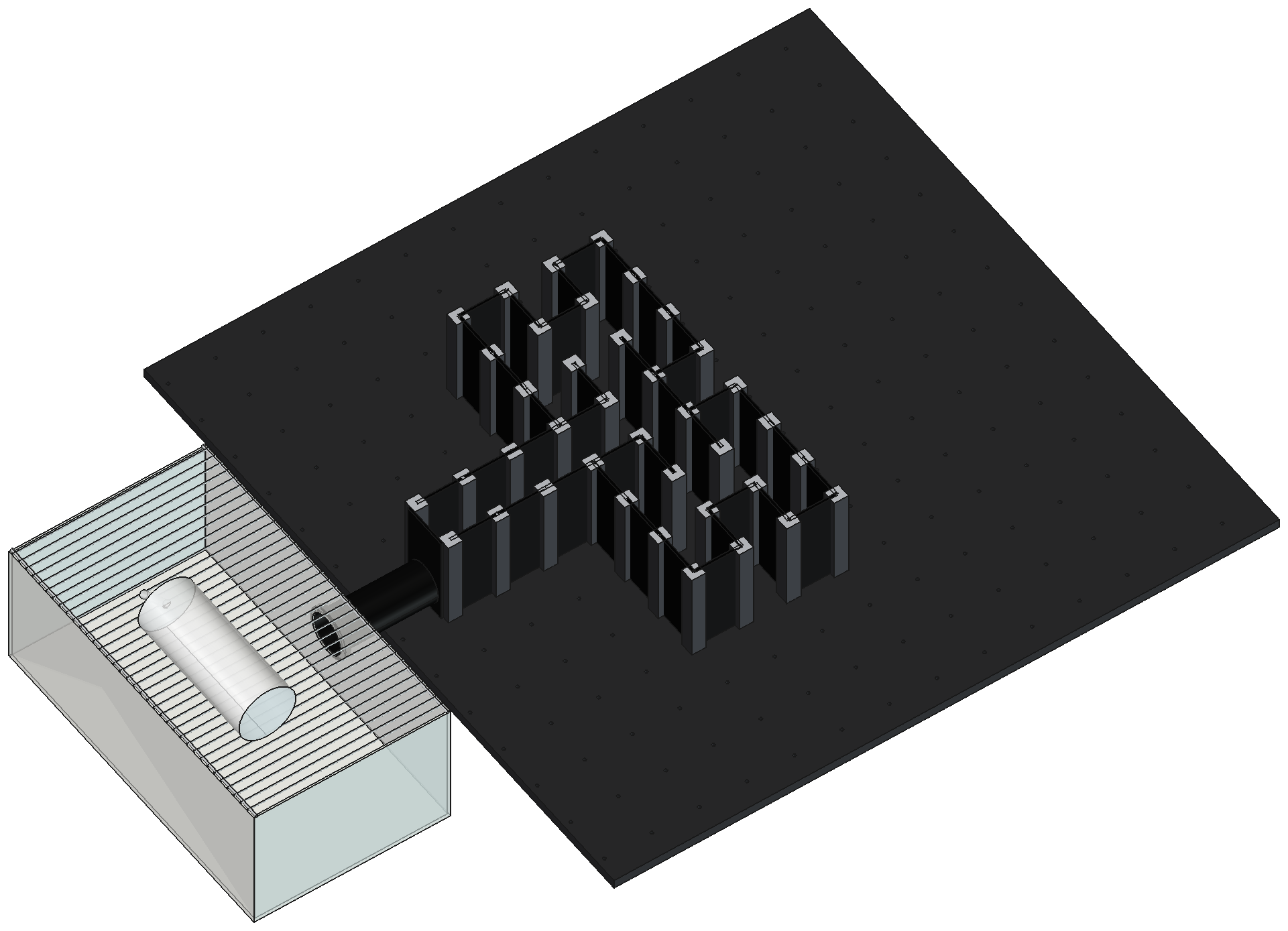
With the covers off, the construction is visible: acrylic panels seated in the slots of the posts, which are bolted through the drilled plate. Any panel position can carry a plain wall or a stimulus device, so the arrangement of the arms is a matter of which positions are filled.
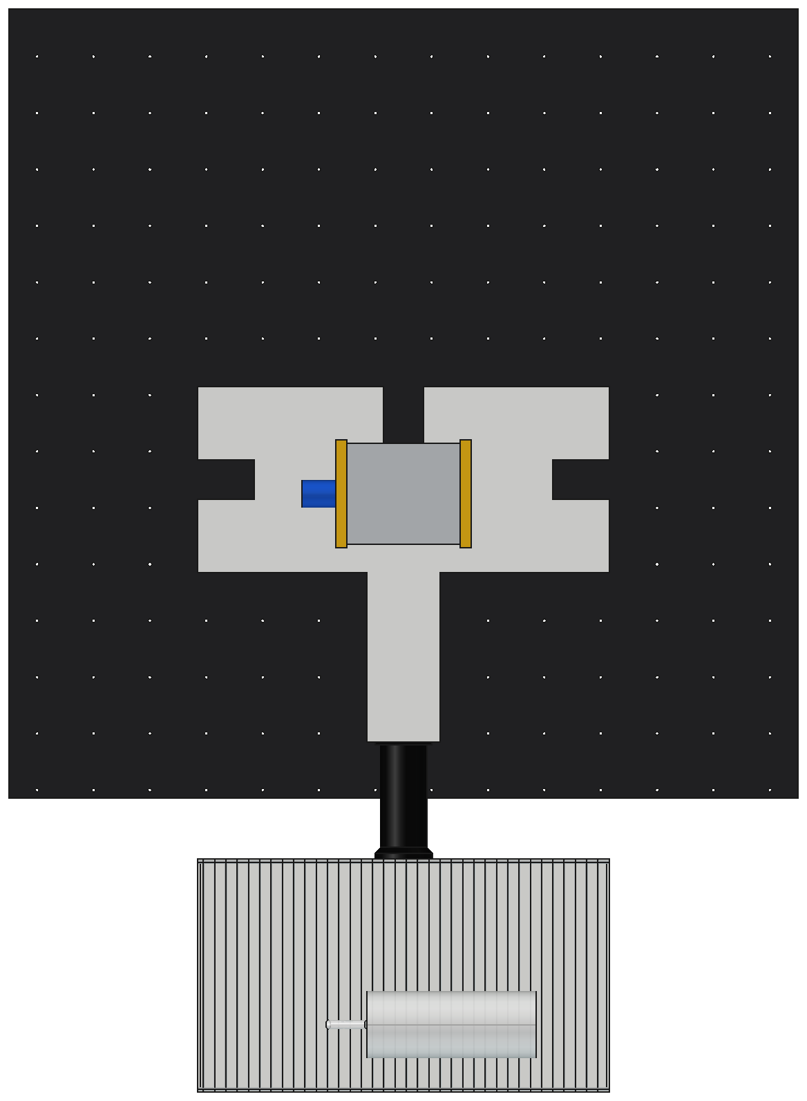
From above, with the covers on as the experiments ran. The covers follow the outline of the arms, the loudspeaker is centred over the maze so that no arm is nearer to it than another, and the tunnel runs from the central corridor out to the cage.
Regenerating the walls and posts
Only needed if the maze layout changes.
hardware/3dmodels/eight_arm_maze/build_maze_model.py turns the layout into
panels, posts and a floor plate, and writes a FreeCAD document along with STEP
and STL versions, under a different name so it cannot overwrite the model above.
Run it inside FreeCAD, from Macro > Macros..., or headless:
Without FreeCAD it still reports what it would build, which is the quickest way to check a dimension or a part count:
layout    maze_layout.json: 21 floor squares, 37 panels, 8 detection regions
maze      350 x 300 mm, centred on a 700 x 700 mm plate
panels    100 x 50 x 3 mm acrylic (height x width x thickness)
posts     15 x 15 mm MakerBeam XL, 100 mm long
parts
     1  Baseplate
    37  Panels
    38  Posts
This configuration uses the taller 100 mm panels, on 100 mm posts. The four-arm tactile maze uses the 50 mm panels on 50 mm posts. The other part dimensions are on the dimensions page.